 Hello,
for my new frame relay switch I was looking for a full mesh configuration. With this I could create different logical connections between the routers using frame relay just by changing the configuration.
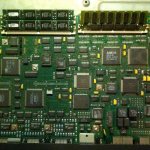
My new frame relay switch is a Cisco 2520 router with 4 serial interface called Serial0, Serial1, Serial2 and Serial3. The configuration for 4 interfaces is not so hard, but I wanted to be flexible for the future (maybe only 3 or maybe a new router with up to 8 serial interfaces).
So I created the following perl script to create the configuration for a frame relay switch.
#!/usr/bin/perl -w
# frs_conf.pl
# 20120216 crissa for http://blog.rotten.li

use strict;

# main
{
  my $first     = 0;        # start with interface 0
  my $last      = 3;        # 4 interfaces (0 - 3)
  my $interface = "Serial"; # "Serial" or "Serial0/" or ...

  # to avoid problems with the dlci for interface 0
  $first++;
  $last++;

  print "!\n";
  print "! config created by frs_conf.pl (http://blog.rotten.li)\n";
  print "!\n";
  print "frame-relay switching\n"; # switch on frame relay
  print "!\n";

  for (my $i = $first; $i <= $last; $i++) {
    printf "interface %s%d\n", $interface, ($i - 1);
    printf " description %d0x\n", $i;

    print <<END;
 bandwidth 64
 no ip address
 encapsulation frame-relay
 no ip route-cache
 logging event subif-link-status
 logging event dlci-status-change
 clock rate 64000
 cdp enable
 no frame-relay inverse-arp
 frame-relay intf-type dce
END

    for (my $j = $first; $j <= $last; $j++) {
      next if ($i == $j); # no route to ourself

      printf " frame-relay route %d0%d interface Serial%d %d0%d\n", \
             $i, $j, ($j-1), $j, $i;
    }

    print "!\n";
  }
}
# main

# eof
And here is the output for my Cisco 2520 router.
!
! config created by frs_conf.pl (http://blog.rotten.li)
!
frame-relay switching
!
interface Serial0
 description 10x
 bandwidth 64
 no ip address
 encapsulation frame-relay
 no ip route-cache
 logging event subif-link-status
 logging event dlci-status-change
 clock rate 64000
 cdp enable
 no frame-relay inverse-arp
 frame-relay intf-type dce
 frame-relay route 102 interface Serial1 201
 frame-relay route 103 interface Serial2 301
 frame-relay route 104 interface Serial3 401
!
interface Serial1
 description 20x
 bandwidth 64
 no ip address
 encapsulation frame-relay
 no ip route-cache
 logging event subif-link-status
 logging event dlci-status-change
 clock rate 64000
 cdp enable
 no frame-relay inverse-arp
 frame-relay intf-type dce
 frame-relay route 201 interface Serial0 102
 frame-relay route 203 interface Serial2 302
 frame-relay route 204 interface Serial3 402
!
interface Serial2
 description 30x
 bandwidth 64
 no ip address
 encapsulation frame-relay
 no ip route-cache
 logging event subif-link-status
 logging event dlci-status-change
 clock rate 64000
 cdp enable
 no frame-relay inverse-arp
 frame-relay intf-type dce
 frame-relay route 301 interface Serial0 103
 frame-relay route 302 interface Serial1 203
 frame-relay route 304 interface Serial3 403
!
interface Serial3
 description 40x
 bandwidth 64
 no ip address
 encapsulation frame-relay
 no ip route-cache
 logging event subif-link-status
 logging event dlci-status-change
 clock rate 64000
 cdp enable
 no frame-relay inverse-arp
 frame-relay intf-type dce
 frame-relay route 401 interface Serial0 104
 frame-relay route 402 interface Serial1 204
 frame-relay route 403 interface Serial2 304
!
If the first router is connected to port Serial0 and the second router is connected to port 3 of the frame relay switch you have to use "1" for the first and "4" for the second router. So the "frame-relay interface-dlci" value for the first router is 104 and for the second 401. (The "0" is just a separator.)
HTH!
Bye, Tore
